Type a search term to find related articles by LIMS subject matter experts gathered from the most trusted and dynamic collaboration tools in the laboratory informatics industry.

Balanced rudders are used by both ships[1] and aircraft. Both may indicate a portion of the rudder surface ahead of the hinge, placed to lower the control loads needed to turn the rudder. For aircraft the method can also be applied to elevators and ailerons; all three aircraft control surfaces may also be mass balanced, chiefly to avoid aerodynamic flutter.
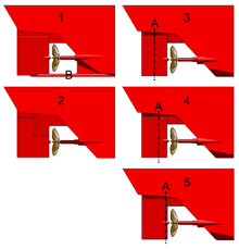
A balanced rudder is a rudder in which the axis of rotation of the rudder is behind its front edge. This means that when the rudder is turned, the pressure of water caused by the ship's movement through the water acts upon the forward part to exert a force which increases the angle of deflection, so counteracting the pressure acting on the after part, which acts to reduce the angle of deflection. A degree of semi-balance is normal to avoid rudder instability i.e. the area in front of the pivot is less than that behind. This allows the rudder to be moved with less effort than is necessary with an unbalanced rudder. However, it is more common on smaller ships as the torque is insufficient for heavier ships.[1]

Balanced rudders were probably first used in the early 15th century, in Ming China's treasure ships,[2] and were reinvented and first used in modern ships by Isambard Kingdom Brunel on the SS Great Britain, launched in 1843.[3]


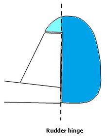
Control of aircraft is complicated by their motion in three dimensions, yaw, pitch and roll, rather than one but there is a similar need to reduce loads, tackled in the same way as on a ship with some part of the surface extending forward of its hinge. This is referred to as aerodynamical balance. In addition, because aircraft control surfaces are mounted on flexible structures like wings, they are prone to oscillate ("flutter"), a dangerous effect which can be cured by bringing the centre of gravity (c.g.) of the control surface to the hinge line. This is called mass balancing.[4]
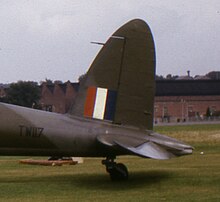
The principle is used on rudders, elevators and ailerons, with methods refined over the years. Two illustrations of aircraft rudders, published by Flight Magazine in 1920,[5] illustrate early forms, both with curved leading and trailing edges. Both are mounted so that the area of the balancing surface ahead of the hinge is less than that of the rudder behind. Various layouts have been tried over the years, generally with smaller balance/rudder areas. Most fall into one of two categories: horn balanced, with small extensions of the control surfaces ahead of the hinge lines at their tips, or inset balanced with extension(s) of the control surface into cut-outs in their supporting fixed surface. Frise ailerons use a variant of the latter balance, with the nose of the up-going surface projecting below the wing, but not vice versa, to provide both balancing and asymmetric drag. Irving balanced ailerons have no projections but harness the aileron deflection induced change of pressure above and below the wing, sensed via the hinge gap, to assist the motion.[4]
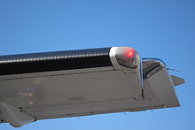
Flutter occurs when the control surface is displaced from its intended deflection. Because the ailerons are on the long, narrow wings which can twist under load, they are the surface most prone to oscillate. If the centre of gravity is behind the hinge, the surface can move like a pendulum and undergo forced simple harmonic motion with increasing amplitude. Adding balancing weights which make the centre of gravity and hinge line coincident solves the problem. These weights may be in the nose of the surface, or lighter masses attached further ahead of the hinge externally.[4]
Oscar Parkes British Battleships ISBN 0-85052-604-3